
Page 156 - REPOWER REFERENCE GUIDE (2020)
P. 156
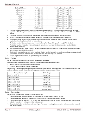
Battery and Electrical

                      Engine (Cyl/Type)          Displacement               Cranking Battery Required Rating
                       V6 carbureted             4.3 L (262 cid)               375 cca, 475 mca, 90 Ah
                       V8 carbureted             5.0 L (305 cid)               375 cca, 475 mca, 90 Ah
                       V8 carbureted             5.7 L (350 cid)               375 cca, 475 mca, 90 Ah
                          V6 MPI                 4.3 L (262 cid)               750 cca, 950 mca, 180 Ah
                          V6 MPI                 4.5 L (275 cid)               750 cca, 950 mca, 180 Ah
                          V8 MPI                 5.0 L (305 cid)               750 cca, 950 mca, 180 Ah
                          V8 MPI                 5.7 L (350 cid)               750 cca, 950 mca, 180 Ah
                          V8 MPI                 6.2 L (377 cid)               750 cca, 950 mca, 180 Ah
                          V8 MPI                 8.1 L (496 cid)               750 cca, 950 mca, 180 Ah
                          V8 MPI                All DTS models                800 cca, 1000 mca, 190 Ah
           •   The reserve capacity rating of the battery must be selected based upon the electrical accessory loads of the particular
               application. Refer to applicable standards and recommended practices for small craft as listed in section E9 of the ABYC
               manual.
           •   The battery should be located as close to the engine as possible and in an accessible location for service.
           •   Be sure the battery compartment is properly vented in accordance with industry standards and regulations.
           •   Properly secure the battery in accordance with industry standards and regulations. Some standards and regulations
               require that the battery be installed in an enclosed case.
           •   The battery must not be installed above or below a fuel tank, fuel filter, or fitting in a fuel line (ABYC standard).
           •   The battery must be installed so that metallic objects cannot come in contact with the ungrounded (positive) battery
               terminal (ABYC standard).
           •   Fuel system components within 31 cm (12 in.) and above the horizontal plane of the battery top surface must be shielded
               with dielectric material (ABYC standard).
           •   Continuously energized parts, such as the positive (+) battery terminal and cable connections must be physically protected
               with boots or other forms of protection to prevent accidental short circuits (ABYC standard).
           •   Multiple engine installations require special battery considerations.
        Battery Cables
           NOTE: The battery should be located as close to the engine as possible.
           Select the proper size positive (+) and negative (–) battery cables using the following chart.
           1.  Add the positive and negative cable lengths together.
           2.  Divide by two to obtain the average cable length.
           IMPORTANT: The terminals must be soldered to cable ends to ensure good electrical contact. Use electrical grade (resin flux)
           solder only. Do not use acid flux solder, as it may cause corrosion and a subsequent failure.
                    Average Cable Length                    Cable Gauge
                                                                  2
            Up to 1.1 m (3½ ft)                              25 mm  (4)
                                                                  2
            1.1–1.8 m (3½–6 ft)                              35 mm  (2)
                                                                  2
            1.8–2.3 m (6–7½ ft)                              50 mm  (1)
                                                                  2
            2.3–2.9 m (7½–9½ ft)                             50 mm  (0)
                                                                  2
            2.9–3.7 m (9½–12 ft)                            70 mm  (00)
                                                                 2
            3.7–4.6 m (12–15 ft)                            95 mm  (000)
                                                                 2
            4.6–5.8 m (15–19 ft)                           120 mm  (0000)
        Battery Connection
           IMPORTANT:  Engine electrical system is negative (–) ground.
           1.  Connect the engine positive (+) battery cable (usually red) to the positive (+) battery terminal.
           2.  Connect the engine negative (–) battery cable (usually black) to the negative (–) battery terminal.
           3.  Connect the power trim pump black (–) battery cable to the negative (–) battery terminal and the trim pump red (+) battery
               cable to the positive (+) battery terminal or battery switch.
           4.  Ensure that all battery terminal connections are tight. Then spray the battery terminals with a battery connection sealant to
               help retard corrosion.


        Page 6C-4                      © 2019 Mercury Marine                    90-8M0149179 eng NOVEMBER 2018