
Page 159 - REPOWER REFERENCE GUIDE (2020)
P. 159
Battery and Electrical
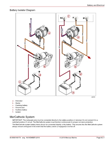
Battery Isolator Diagram
f
B2 A B1
RED/PPL RED/PPL
PPL a PPL
ORN
a
ORN
ORN BLK ORN BLK
RED
RED
RED b b
d d
BLK BLK
c BLK BLK
e
24376
a - Alternator
b - Starter
c - Cranking battery
d - Ground stud
e - Auxiliary battery
f - Isolator
MerCathode System
IMPORTANT: The red/purple wire must be connected directly to the battery positive (+) terminal. Do not connect it to a
switched positive (+) circuit. The MerCathode system must function continuously for proper corrosion protection.
The MerCathode system battery leads should be connected directly to the battery. This ensures that the MerCathode system
always remains energized in the event that the battery switch (if equipped) is turned off.
90-8M0149179 eng NOVEMBER 2018 © 2019 Mercury Marine Page 6C-7