
Page 236 - REPOWER REFERENCE GUIDE (2020)
P. 236
Single Catalyst V8 Engines
a. Remove the shift plate.
a
a - Mounting screws (two shown, one hidden)
b - Shift plate
b
50914
b. Remove the fuse and relay bracket.
a
a - Mounting screws (2)
b - Fuse and relay bracket
b
50915
3. Drain the engine coolant:
a. On seawater‑cooled models, drain the seawater section of the engine. Refer to Section 1C.
b. On models with closed cooling, drain the coolant until the level is below the exhaust elbow joint area. Refer to the
Draining procedure in Section 6C.
c. Note the locations and connections of the hoses for reassembly.
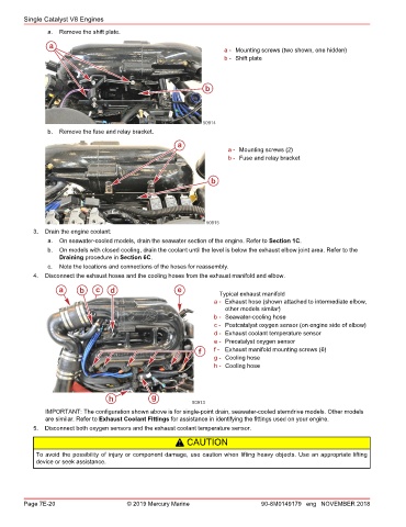
4. Disconnect the exhaust hoses and the cooling hoses from the exhaust manifold and elbow.
a b c d e Typical exhaust manifold
a - Exhaust hose (shown attached to intermediate elbow,
other models similar)
b - Seawater‑cooling hose
c - Postcatalyst oxygen sensor (on engine side of elbow)
d - Exhaust coolant temperature sensor
e - Precatalyst oxygen sensor
f f - Exhaust manifold mounting screws (6)
g - Cooling hose
h - Cooling hose
h g
50913
IMPORTANT: The configuration shown above is for single‑point drain, seawater‑cooled sterndrive models. Other models
are similar. Refer to Exhaust Coolant Fittings for assistance in identifying the fittings used on your engine.
5. Disconnect both oxygen sensors and the exhaust coolant temperature sensor.
! CAUTION
To avoid the possibility of injury or component damage, use caution when lifting heavy objects. Use an appropriate lifting
device or seek assistance.
Page 7E-20 © 2019 Mercury Marine 90-8M0149179 eng NOVEMBER 2018