Page 239 - REPOWER REFERENCE GUIDE (2020)
P. 239

Single Catalyst V8 Engines
                   Description                                                          Nm        lb‑in.      lb‑ft
                                                                    First                27         –         20
                   Manifold mounting screws                         Second               41         –         30
                                                                    Final                54         –         40
               7.  Install the catalyst and elbow, if removed. Refer to Exhaust Elbow Installation.
               8.  Attach all cooling hoses, securing them with hose clamps.
               9.  Connect the exhaust hoses, securing them with two hose clamps at each connection point.
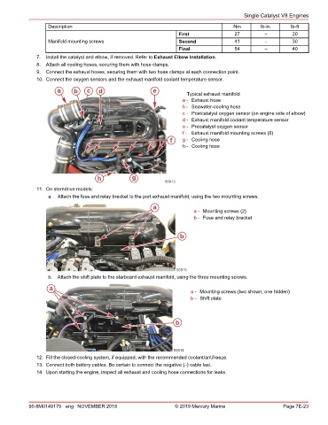
               10. Connect the oxygen sensors and the exhaust manifold coolant temperature sensor.
                      a      b   c    d                   e            Typical exhaust manifold
                                                                     a - Exhaust hose
                                                                     b - Seawater‑cooling hose
                                                                     c - Postcatalyst oxygen sensor (on engine side of elbow)
                                                                     d - Exhaust manifold coolant temperature sensor
                                                                     e - Precatalyst oxygen sensor
                                                                     f - Exhaust manifold mounting screws (6)
                                                                 f   g - Cooling hose
                                                                     h - Cooling hose


                                     h            g
                                                               50913
               11. On sterndrive models:
                   a.  Attach the fuse and relay bracket to the port exhaust manifold, using the two mounting screws.
                                                          a
                                                                         a - Mounting screws (2)
                                                                         b - Fuse and relay bracket


                                                                    b


                                                                   50915
                   b.  Attach the shift plate to the starboard exhaust manifold, using the three mounting screws.
                   a
                                                                        a - Mounting screws (two shown, one hidden)
                                                                        b - Shift plate


                                                                   b


                                                                  50914
               12. Fill the closed‑cooling system, if equipped, with the recommended coolant/antifreeze.
               13. Connect both battery cables. Be certain to connect the negative (–) cable last.
               14. Upon starting the engine, inspect all exhaust and cooling hose connections for leaks.


            90-8M0149179 eng NOVEMBER 2018                        © 2019 Mercury Marine                    Page 7E-23
   234   235   236   237   238   239   240   241   242   243   244