
Page 276 - REPOWER REFERENCE GUIDE (2020)
P. 276
Critical Procedures
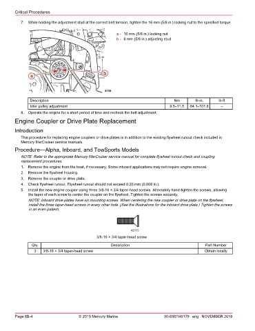
7. While holding the adjustment stud at the correct belt tension, tighten the 16 mm (5/8 in.) locking nut to the specified torque.
a - 16 mm (5/8 in.) locking nut
b - 8 mm (5/8 in.) adjusting stud
a b
6119
Description Nm lb‑in. lb‑ft
Idler pulley adjustment 9.5–11.5 84.1–101.8 –
8. Operate the engine for a short period of time and recheck the belt adjustment.
Engine Coupler or Drive Plate Replacement
Introduction
This procedure for replacing engine couplers or drive plates is in addition to the existing flywheel runout check included in
Mercury MerCruiser service manuals.
Procedure—Alpha, Inboard, and TowSports Models
NOTE: Refer to the appropriate Mercury MerCruiser service manual for complete flywheel runout check and coupling
replacement procedures.
1. Remove the engine from the boat, if necessary. Some inboard applications may not require engine removal.
2. Remove the flywheel housing.
3. Remove the coupler or drive plate.
4. Check flywheel runout. Flywheel runout should not exceed 0.20 mm (0.008 in.).
5. Install the new engine coupler using three 3/8‑16 × 3/4 taper‑head screws. Alternately hand‑tighten the screws, allowing
the taper of each screw to center the coupler on the flywheel. Tighten the screws securely.
NOTE: Inboard drive plates have six mounting screws. When centering the new coupler or drive plate on the flywheel,
install the three taper‑head screws in every other hole. (See the illustrations for the inboard drive plate.) Tighten the screws
in an even pattern.
42059
3/8-16 × 3/4 taper-head screw
Qty. Description Part Number
3 3/8‑16 × 3/4 taper‑head screw Obtain locally
Page 8B-4 © 2019 Mercury Marine 90-8M0149179 eng NOVEMBER 2018