
Page 316 - REPOWER REFERENCE GUIDE (2020)
P. 316
Shift and Throttle Cable Installation
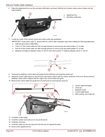
6. Place the adjustment tool over the sterndrive shift cable, as shown. Hold the tool in place using a piece of tape over the
barrel retainer.
a
a - Adjustment tool
b - Sterndrive shift cable
b
21615
7. Locate the center of the remote control and control cable play (backlash).
IMPORTANT: Keep center mark "C" aligned with the control cable end guide edge when making the following adjustment.
a. Shift remote control to NEUTRAL.
b. Push in on the control cable end with enough pressure to remove play and mark position "a" on tube.
c. Pull out on the control cable end with enough pressure to remove play and mark position "b" on tube.
d. Measure the distance between marks "a" and "b" and mark position "c" halfway between marks "a" and "b".
c
a 7815
b
8. Temporarily install the control cable end guide into the shift lever and insert the anchor pin.
9. Adjust the control cable barrel so that the hole in the barrel centers with the vertical centerline of the stud. Ensure that the
backlash center mark is aligned with the edge of the control cable end guide.
10. Remove the control cable end guide from the shift lever by removing the clevis pin.
c d a - Control cable end guide
b - Clevis pin
c - Backlash center
d - Control cable barrel
a e - Stud, washer, and cotter pin
c d
b
e
21613
11. Install the control cable.
12. Install the washer and cotter pin to secure the barrel.
13. Install the clevis pin.
14. Install the cotter pin into the clevis pin from the top and spread the ends.
15. Remove the adjustment tool.
Page 9A-8 © 2019 Mercury Marine 90-8M0149179 eng NOVEMBER 2018