
Page 319 - REPOWER REFERENCE GUIDE (2020)
P. 319
Shift and Throttle Cable Installation
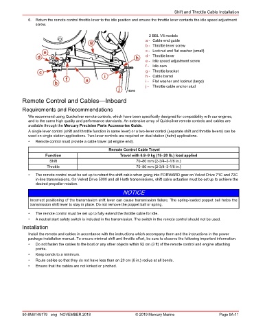
6. Return the remote control throttle lever to the idle position and ensure the throttle lever contacts the idle speed adjustment
screw.
2 BBL V8 models
g a - Cable end guide
b - Throttle lever screw
e c - Locknut and flat washer (small)
d h d - Throttle lever
e - Idle speed adjustment screw
f - Idle cam
c g - Throttle bracket
h - Cable barrel
f a i i - Flat washer and locknut (large)
b j - Throttle cable anchor stud
j 9378
Remote Control and Cables—Inboard
Requirements and Recommendations
We recommend using Quicksilver remote controls, which have been specifically designed for compatibility with our engines,
and to the same high quality and performance standards. An extensive array of Quicksilver remote controls and cables are
available through the Mercury Precision Parts Accessories Guide.
A single lever control (shift and throttle function in same lever) or a two‑lever control (separate shift and throttle levers) can be
used on single station applications. Two‑lever controls are required on dual station (helm) applications.
• Remote control must provide a cable travel (at engine end).
Remote Control Cable Travel
Function Travel with 6.8–9 kg (15–20 lb.) load applied
Shift 70–80 mm (2‑3/4–3‑1/8 in.)
Throttle 70–80 mm (2‑3/4–3‑1/8 in.)
• The remote control must be set up to retract the shift cable when going into FORWARD gear on Velvet Drive 71C and 72C
in‑line transmissions. On Velvet Drive 5000 and all Hurth transmissions, shift cable actuation must be set up to achieve the
desired propeller rotation.
NOTICE
Incorrect positioning of the transmission shift lever can cause transmission failure. The spring‑loaded poppet ball helps the
transmission shift lever to stay in place. Do not remove the poppet ball or spring.
• The remote control must be set up to fully extend the throttle cable for idle.
• A neutral start safety switch is included in the transmission. The switch in the remote control should not be used.
Installation
Install the remote and cables in accordance with the instructions which accompany them and the instructions in the power
package installation manual. To ensure minimal shift and throttle effort, be sure to observe the following important information:
• Do not fasten the cables to the boat or any other objects within 92 cm (3 ft) of the remote control and engine attaching
points.
• Keep bends to a minimum.
• Route cables so that they do not have less than an 20 cm (8 in.) radius at all bends.
• Ensure that the cables are not kinked or pinched.
90-8M0149179 eng NOVEMBER 2018 © 2019 Mercury Marine Page 9A-11