
Page 342 - REPOWER REFERENCE GUIDE (2020)
P. 342
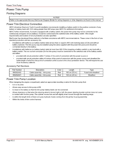
Power Trim Pump
        Power Trim Pump

        Finding Diagrams

                                                           NOTICE
            Refer to the appropriate Mercury MerCruiser Diagram Binder for wiring diagrams or other diagrams not found in this manual.
        Power Trim Electrical Connection

           ABYC (American Boat and Yacht Council) installation recommends installing a battery switch in the positive conductor of any
           battery or battery bank with CCA rating greater than 800 amps (see ABYC for additional information).
           ABYC further recommends, if a boat is equipped with a battery switch, the power trim pump may not be connected to the
           continuously energized circuit (battery). It must be connected to the switched side of the battery switch. Wire length
           requirements and location of circuit protection are also specified.
           MerCruiser has developed three methods to facilitate compliance with ABYC recommendations. These come in the form of one
           standard production and two accessory kits.
           •   Installations with batteries (or battery banks) rated at less than or equal to 800 cold cranking amps (CCA) and without
               battery switches: The trim pump may be installed using the wires supplied with the power trim pump and should be
               connected directly to the battery.
           •   Installations with batteries (or battery banks) rated at more than 800 CCAs (requiring a battery switch) or any boat with a
               battery switch: The red current conductor (for the trim pump) must be connected to the switched side of the battery switch
               and either:
               •   provided with circuit protection within 7 inches of the point of connection with the power source or
               •   provided with circuit protection within 40 inches of the point of connection with the power source and sheathed the
                   entire length of wire from the point of connection at the source to the circuit protection device. This will require the use
                   of an Accessory cable kit.

        Accessory Part Numbers
              Part Number               Description            Color        Length                Type
               889282A02         Cable assembly – trim pump     Red      183 cm (72 in.)    Fused and sheathed
               889282A01         Cable assembly – trim pump     Red      102 cm (40 in.)         Sheathed
        Power Trim Pump Location
           When designing the engine compartment, select an appropriate mounting location for the trim pump that:
           •   Is in a dry area
           •   Allows easy access to trim pump oil fill
           •   Is close to the battery so that the trim pump battery leads can be connected
           •   Allows clearance so that when the steering wheel is turned right or left, the power steering booster cylinder does not come
               in contact with the trim pump. The cylinder moves fore and aft slightly when moved through the steering range.
           •   Is within the length limits of black and gray hydraulic hoses coming from the gimbal housing assembly
           •   Within the limits of trim control harness


        Page 9C-2                      © 2019 Mercury Marine                    90-8M0149179 eng NOVEMBER 2018