Page 245 - Toro Irrigation Product Catalogue August 2020
P. 245

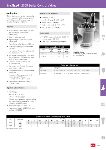
200B Series Control Valves
                      R


        Application                           Electrical Specifications

         These durable, heavy-duty commercial
         valves are designed to provide reliable,   •  Solenoid: 24 VAC
         cost-effective performance under the   •  Inrush volt-amp: 24 VAC–9.6 VA
         most challenging conditions.         •  Inrush current: 0.4 amp
                                              •  Holding volt-amp: 24 VAC–4.8 VA
         Features                             •  Holding current: 0.2 amp

         •  Double-beaded diaphragm provides
           leak proof seal. Santoprene        Accessories
           construction.
         •  Buna-N valve seat seal            •  9–12 VDC Latching Solenoid (DCLS-P)
         •  High-strength ribbed bonnet and     (max. pressure 820 kPa)
           bottom inlet                       •  OmniReg  Pressure Regulating Kit
                                                       ®
         •  Manual internal and external bleeds
         •  Slow-closing design reduces water       Dimensions (L × W × H)
           hammer
         •  Flow control allows flow adjustment   Code  Length    Width    Height
                                                                          (mm)
                                                                  (mm)
                                                         (mm)
           and manual shutoff                                                      The 200B Series
                                               216B-M    140      108     197      40 mm and 50 mm, solid construction,
         •  Heavy-duty, construction. Corrosion-                                   proven reliability
           and UV-resistant PVC with stainless   217B-M  160      138     223
           steel spring and hardware
         •  Threaded inlet plug O-ring seal
           minimises leaks
         •  Captive plunger feature eliminates                       Ordering Information
           loose parts in solenoid            Code           Description
         •  Easily serviced without removal from   216B-M    40 mm Model 200B Solenoid Valve with Flow Control
           the system                         217B-M         50 mm Model 200B Solenoid Valve with Flow Control
         •  Three-way stainless steel bonnet
           screws accept Phillips,
           flat-blade and hex-driver tools
         •  Pressure regulation: OmniReg
                                   ®
           modular option

         Operating Specifications

         •  Flow Range:
           40 mm: 80 to 300 Lpm
           50 mm: 225 to 450 Lpm
           Consult your irrigation designer before
           using any solenoid valve where flow
           velocities exceed 2 m/sec
         •  Pressure Range: 140–1034 kPa
         •  Maximum pressure of 820 kPa if using
           latching coil (DCLS-P)


                                         200B Series Valve Friction Loss Data – kPa
                                                                    Flow – Lpm
            Size    Configuration
                                 80    100   120    140   160   180    200   225   250    300   350   400    450
           40 mm      Globe      21    19     18    16    17     19    23    28     32    39
                                                          14
                                                                 15
                                                                                    24
                                                                                          30
                                                                       17
                                                                             11
                                 19
                                       17
                                              15
                      Angle
                                                    14
                      Globe                                                  12     14    20    29     36    43
           50 mm
                      Angle                                                  11     12    15    19     26    33
        Shading indicates flow range.
                                                                                                              229
   240   241   242   243   244   245   246   247   248   249   250