
Page 66 - C:\Users\trainee\AppData\Local\Temp\msoEAA3.tmp
P. 66
Document Title
Fundamentals of Stress and Vibration Chapter Title
[A Practical guide for aspiring Designers / Analysts] 2. Engineering Mechanics
Ǯǯ ȏ ʹǤͷȐǤ
ǡ ǣ
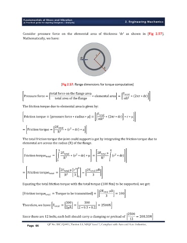
[Fig 2.57: flange dimensions for torque computation]
total force on the flange area F total
Pressure force = ∗ elemental area = ∗ 2πr ∗ dr
total area of the flange πR 2
The friction torque due to elemental area is given by:
F total
Friction torque = pressure force ∗ radius ∗ μ = ∗ 2πr ∗ dr ∗ r ∗ μ
πR 2
2F total
2
= Friction torque = ∗ r ∗ dr ∗ μ
R 2
The total friction torque the joint could support is got by integrating the friction torque due to
elemental are across the radius (R) of the flange.
R R
2F total 2F total μ
2
2
Friction torque total = ∗ r ∗ dr ∗ μ = r ∗ dr
R 2 R 2
0 0
2F total μ r 3 R 2F total μR
= Friction torque = =
total
R 2 3 3
0
Equating the total friction torque with the total torque (100 Nm) to be supported, we get:
2F μR
Friction torque total = Torque to be transmitted = total = 100
3
300 300
Therefore, we have: F total = = = 2500N
2μR 2 ∗ 0.3 ∗ 0.2
2500
Since there are 12 bolts, each bolt should carry a clamping or preload of = 208.33N
12
Page 66 QP No. SSC/Q4401, Version 1.0, NSQF Level 7, Compliant with Aero and Auto Industries,