Page 257 - Fisika Terapan for Engineers and Scientists
P. 257

Problems                              457


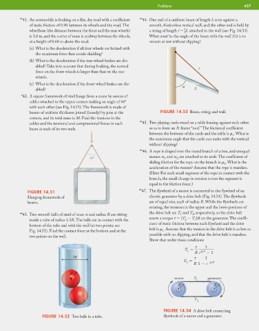
                     **41. An automobile is braking on a flat, dry road with a coefficient  **44. One end of a uniform beam of length L rests against a
                         of static friction of 0.90 between its wheels and the road. The  smooth, frictionless vertical wall, and the other end is held by
                                                                                              3
                         wheelbase (the distance between the front and the rear wheels)  a string of length l   L attached to the wall (see Fig. 14.53).
                                                                                              2
                         is 3.0 m, and the center of mass is midway between the wheels,  What must be the angle of the beam with the wall if it is to
                         at a height of 0.60 m above the road.                remain at rest without slipping?
                         (a) What is the deceleration if all four wheels are braked with
                            the maximum force that avoids skidding?
                         (b) What is the deceleration if the rear-wheel brakes are dis-
                            abled? Take into account that during braking, the normal
                                                                                                    l
                            force on the front wheels is larger than that on the rear
                            wheels.
                         (c) What is the deceleration if the front-wheel brakes are dis-
                                                                                             a
                            abled?                                                                L
                      *42. A square framework of steel hangs from a crane by means of
                         cables attached to the upper corners making an angle of 60
                         with each other (see Fig. 14.51). The framework is made of
                         beams of uniform thickness joined (loosely) by pins at the  FIGURE 14.53 Beam, string, and wall.
                         corners, and its total mass is M. Find the tensions in the
                         cables and the tensional and compressional forces in each  **45. Two playing cards stand on a table leaning against each other
                         beam at each of its two ends.                        so as to form an A-frame “roof.” The frictional coefficient
                                                                              between the bottoms of the cards and the table is   . What is
                                                                                                                   s
                                                                              the maximum angle that the cards can make with the vertical
                                                                              without slipping?
                                                                          **46. A rope is draped over the round branch of a tree, and unequal
                                                                              masses m and m are attached to its ends. The coefficient of
                                                                                          2
                                                                                     1
                                                                              sliding friction for the rope on the branch is   . What is the
                                                                                                               k
                                                                              acceleration of the masses? Assume that the rope is massless.
                                                                              (Hint: For each small segment of the rope in contact with the
                                                                              branch, the small change in tension across the segment is
                                                                              equal to the friction force.)
                         FIGURE 14.51                                     **47. The flywheel of a motor is connected to the flywheel of an
                         Hanging framework of                                 electric generator by a drive belt (Fig. 14.54). The flywheels
                         beams.                                               are of equal size, each of radius R. While the flywheels are
                                                                              rotating, the tensions in the upper and the lower portions of
                                                                              the drive belt are T and T , respectively, so the drive belt
                     **43. Two smooth balls of steel of mass m and radius R are sitting     1    2
                                                                              exerts a torque     (T   T )R on the generator. The coeffi-
                         inside a tube of radius 1.5R. The balls are in contact with the      2   1
                                                                              cient of static friction between each flywheel and the drive
                         bottom of the tube and with the wall (at two points; see
                                                                              belt is   . Assume that the tension in the drive belt is as low as
                         Fig. 14.52). Find the contact force at the bottom and at the  s
                                                                              possible with no slipping, and that the drive belt is massless.
                         two points on the wall.
                                                                              Show that under these conditions
                                                                                                       1
                                                                                              T          s
                                                                                               1
                                                                                                  R e     1
                                            3R                                                         1
                                                                                             T
                                                                                              2            s
                                                                                                  R 1   e
                                           R
                                                                                         motor    T 1   generator
                                                                                           R               R

                                                                                                  T  2

                                                                                    FIGURE 14.54 A drive belt connecting
                               FIGURE 14.52 Two balls in a tube.                    flywheels of a motor and a generator.
   252   253   254   255   256   257   258   259   260   261   262