
Page 17 - Physics Form 5 KSSM_Neat
P. 17
The magnitude and direction of two forces that are at an angle with each other can be CHAPTER 1
determined by practical means using a Vector Force Table Kit.
Activity 1.3 Force and Motion II
Aim: To determine the magnitude and direction of the resultant force of two forces that make an
KEMENTERIAN PENDIDIKAN MALAYSIA
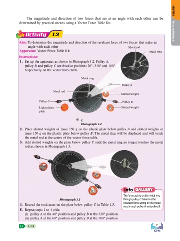
angle with each other Metal rod
Apparatus: Vector Force Table Kit Metal ring
Instructions:
1. Set up the apparatus as shown in Photograph 1.2. Pulley A,
pulley B and pulley C are fixed at positions 20°, 340° and 180°
respectively on the vector force table.
Metal ring
Pulley A
Metal rod
Slotted weight
Pulley C Pulley B
Light plastic Slotted weight
plate
Photograph 1.2
2. Place slotted weights of mass 150 g on the plastic plate below pulley A and slotted weights of
mass 150 g on the plastic plate below pulley B. The metal ring will be displaced and will touch
the metal rod at the centre of the vector force table.
3. Add slotted weights on the plate below pulley C until the metal ring no longer touches the metal
rod as shown in Photograph 1.3.
Info GALLERY
The force acting on the metal ring
Photograph 1.3 through pulley C balances the
resultant force acting on the metal
4. Record the total mass on the plate below pulley C in Table 1.3. ring through pulley A and pulley B.
5. Repeat steps 1 to 4 with:
(i) pulley A at the 40° position and pulley B at the 320° position
(ii) pulley A at the 60° position and pulley B at the 300° position
LS 1.1.2 7