Page 18 - Physics Form 5 KSSM_Neat
P. 18

Results:
                                                   Table 1.3
                        Pulley A                        Pulley B                   Pulley C
                       Mass /  Force applied /         Mass / Force applied / Mass / Force applied /
             Position                        Position
                         g         N                     g          N          g         N
             KEMENTERIAN PENDIDIKAN MALAYSIA
               20°      150        1.5         340°     150        1.5
               40°      150        1.5         320°     150        1.5
               60°      150        1.5         300°     150        1.5

           Discussion:
            1.  What  is the direction  of the  resultant  force  of the  two forces that  act  on the  metal  ring
              through pulley A and pulley B?
            2.  Why is the magnitude of the force acting on the metal ring through pulley C equal to the
              magnitude of the resultant force?
            3.  How does the magnitude of the resultant force change when the angle between the two
              forces increases?

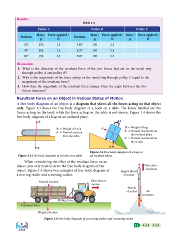
           Resultant Force on an Object in Various States of Motion
           A free body diagram of an object is a diagram that shows all the forces acting on that object
           only. Figure 1.3 shows the free body diagram of a book on a table. The forces labelled are the
           forces acting on the book while the force acting on the table is not shown. Figure 1.4 shows the
           free body diagram of a bag on an inclined plane.
                        R                                                R
                                                                            W = Weight of bag
                                   W = Weight of book         N
                                   R  = Normal reaction                     R  = Normal reaction from
                                       from the table                           the inclined plane
                                                                            N  = Normal reaction from
                                                                                the wedge
                       W                                          W
                                                       Figure 1.4 Free body diagram of a bag on
            Figure 1.3 Free body diagram of a book on a table  an inclined plane
                When considering the effect of the resultant force on an
           object, you only need to draw the free body diagram of the                   Direction
           object. Figure 1.5 shows two examples of free body diagram of   Engine thrust  of motion
           a moving trailer and a moving rocket.                           of rocket

                        Normal reaction                 Direction of
                                                        motion
                                                                              Weight
                                                                             of rocket   Air
                                                                                      resistance

                                    Pulling force
              Frictional force

                        Weight of trailer
                            Figure 1.5 Free body diagram of a moving trailer and a moving rocket
             8                                                                    LS   1.1.2  1.1.3
   13   14   15   16   17   18   19   20   21   22   23