Page 200 - Physics Form 5 KSSM_Neat
P. 200

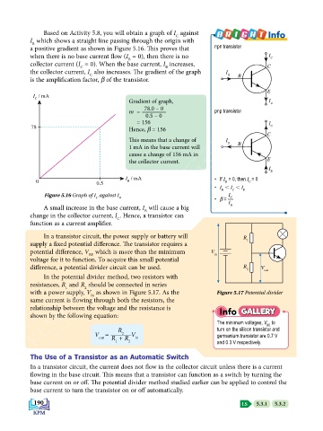
Based on Activity 5.8, you will obtain a graph of I  against               Info
                                                            C
           I  which shows a straight line passing through the origin with
            B
           a positive gradient as shown in Figure 5.16. This proves that   npn transistor
           when there is no base current flow (I  = 0), then there is no                   I C
                                            B
           collector current (I  = 0). When the base current, I  increases,               C
                                                        B
                            C
           the collector current, I  also increases. The gradient of the graph   I
                               C
           is the amplification factor, b of the transistor.                 B   B
            KEMENTERIAN PENDIDIKAN MALAYSIA
                                                                                          E
            I  / mA
                                            Gradient of graph,                             I E
             C
                                                 78.0 – 0
                                            m  =                         pnp transistor
                                                  0.5 – 0
                                               = 156                                       I
           78                               Hence, b = 156                                  C
                                                                                          C
                                            This means that a change of      I B
                                            1 mA in the base current will        B
                                            cause a change of 156 mA in
                                            the collector current.                        E
                                                                                           I
                                                                                            E
                                           I  / mA                       •  If I  = 0, then I = 0
             0                   0.5        B                               B       C
                                                                         •  I  , I  , I
                                                                           B   C  E
                Figure 5.16 Graph of I  against I                            I
                                 C       B                               •  b =   C
                                                                             I
                A small increase in the base current, I  will cause a big     B
                                                 B
           change in the collector current, I . Hence, a transistor can
                                        C
           function as a current amplifier.
                In a transistor circuit, the power supply or battery will         R
           supply a fixed potential difference. The transistor requires a           1
           potential difference, V  which is more than the minimum      V in
                               BE
           voltage for it to function. To acquire this small potential
           difference, a potential divider circuit can be used.                   R 2   V out
                In the potential divider method, two resistors with
           resistances, R  and R  should be connected in series
                             2
                       1
           with a power supply, V  as shown in Figure 5.17. As the        Figure 5.17 Potential divider
                               in
           same current is flowing through both the resistors, the
           relationship between the voltage and the resistance is         Info GALLERY
           shown by the following equation:
                                                                          The minimum voltages, V  to
                                                                                          BE
                                        R                                 turn on the silicon transistor and
                                 V =      2  V                            germanium transistor are 0.7 V
                                  out   R  + R  in
                                        1   2                             and 0.3 V respectively.
           The Use of a Transistor as an Automatic Switch
           In a transistor circuit, the current does not flow in the collector circuit unless there is a current
           flowing in the base circuit. This means that a transistor can function as a switch by turning the
           base current on or off. The potential divider method studied earlier can be applied to control the
           base current to turn the transistor on or off automatically.

            190                                                                   LS     5.3.1     5.3.2
   195   196   197   198   199   200   201   202   203   204   205