
Page 203 - Physics Form 5 KSSM_Neat
P. 203
1. Connect the heat-controlled switch transistor kit to a 6 V direct current power supply. CHAPTER 5
2. Switch on the power supply and observe whether the LED lights up. Electronics
3. Rub your hands together until they become warm and then touch the thermistor. Observe
whether the LED lights up.
Discussion:
KEMENTERIAN PENDIDIKAN MALAYSIA
1. Explain your observations:
(a) after the power supply is switched on
(b) when the thermistor is touched with warm fingers
2. How does the transistor function as an automatic heat-controlled switch?
3. What modifications are needed to be made so that the LED can be replaced with an electric bell?
Formative Practice 5.3
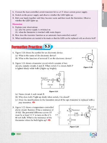
1. Figure 5.20 shows the symbol for an electronic device.
(a) What is the name of the electronic device?
(b) What is the function of terminal X on the electronic device?
X
2. Figure 5.21 shows a transistor circuit which consists of two
circuits, namely circuits A and B. When switch S is closed, bulb P
is lighted dimly while bulb Q lights up brightly. Figure 5.20
Q
Switch S
R
P
Circuit Circuit
A B
Figure 5.21
(a) Name circuit A and circuit B.
(b) Why does bulb P light up dimly when switch, S is closed?
(c) draw the modifications to the transistor circuit if the npn transistor is replaced with a
pnp transistor.
3. Figure 5.22 shows a temperature-controlled 6 V
alarm circuit. Resistor, R has a resistance of R Thermistor 60 mA
10 kW. The potential difference across XY + T 1 kΩ I I C
must be at least 5.5 V to turn on the 6 V, 6 V X B
60 mA bulb. What is the resistance of the –
thermistor when the bulb lights up? R 10 kΩ
Y
Figure 5.22
LS 5.3.2 193