
Page 201 - Physics Form 5 KSSM_Neat
P. 201
Light-dependent resistor in a light-controlled switch CHAPTER 5
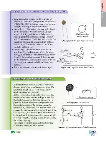
• Light-dependent resistor (LDR) is a type of Electronics
resistor. Its resistance changes with the intensity
of light. The LDR resistance value is high when
KEMENTERIAN PENDIDIKAN MALAYSIA
the light intensity is low and vice versa.
• In the dark, LDR resistance is very high. Based
on the concept of potential divider, voltage
across LDR, V LDR will increase. When the V LDR A light-dependent
value exceeds the minimum voltage across B resistor symbol
and E, base current, I will flow and turn on the
B
transistor. This condition causes high collector Photograph 5.6 A light-dependent resistor
current, I to flow in the collector circuit and
C
the bulb will light up.
• Under bright conditions, resistance of LDR is
low. Thus, V LDR will decrease. When the value R 10 kΩ I C +
of V LDR is less than the minimum voltage across 1 kΩ I B C
B and E, then no base current, I flows to turn B 6 V
B
on the transistor. This situation causes collector E –
current, I not to flow and the bulb does not LDR Light dependent
C
light up. resistor
• This circuit is used in automatic street lights. Figure 5.18 A light-controlled switch circuit
Thermistor in a heat-controlled switch
• A thermistor is a resistor. Its whose resistance
changes with its surrounding temperature. The
resistance is high under room temperature
conditions (low temperature).
• As the surrounding temperature increases, the
resistance becomes low and voltage across the Thermistor symbol
thermistor decreases. Based on the concept of
potential divider, when the voltage across the Photograph 5.7 A thermistor
thermistor decreases, the voltage across the
resistor R, V will increase. When the value of V
R
R
exceeds the minimum voltage across B and E, the Thermistor I
base current, I will flow and the transistor will 1 kΩ I C C +
B
be turned on. This situation will result in a high B 6 V
collector current I flowing in the circuit causing B E –
C
the bulb to light up. R 10 kΩ
• This circuit is suitable as an automatic switch
in a temperature-controlled system.
Figure 5.19 A temperature-controlled alarm circuit
LS 5.3.2 191