
Page 59 - E BOOK ENGINE MECHANICAL M2
P. 59
3. FUEL SYSTEM
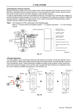
<Fuel Injection Pressure Control>
Based on the pulse output of the crank angle sensor and the intended fuel injection amount, the En-
gine-ECU calculates the fuel injection pressure. It then actuates the suction control valve to control
fuel volume to the common rail, which equates to fuel injection pressure.
In order to appropriately control the fuel injection pressure, the Engine-ECU monitors the voltage out-
put of the pressure sensor located on the common rail. Because this system can maintain a high fuel
injection pressure regardless of engine speed, it can reduce the amount of PM (particulate matter)*
and NOx that are emitted at low engine speeds.
*Note: The substance of PM is described in the following page.
Refer to: “Common Rail Fuel Injection System” →”3. System Operation” →”3. Fuel Pressure
Control”
Fig. 3-7
<Plunger Operation>
The two plungers move reciprocally inside the high-pressure chambers to alternate between fuel in-
take and delivery. When one plunger is performing a fuel intake stroke, the other plunger is perform-
ing a fuel delivery stroke. These movements enable the supply pump to deliver a dual, continuous,
and uninterrupted fuel supply to the common rail to support the dual injection per crankshaft revolu-
tion and to maintain constant fuel pressure in the common rail.
Plunger
Ring cam
Plunger
Fig. 3-8
3 - 5 Pub. No. PTAE1228