Page 64 - E BOOK ENGINE MECHANICAL M2
P. 64

4. SERVICE POINTS OF 4D56 ENGINE COMPONENT


           (3) Timing Belt Installation
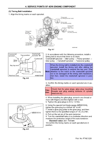
           1. Align the timing marks on each sprocket.


                                                          Fig. 4-7

                                                       2. In accordance with the following procedure, install a
                                                       timing belt to insure that there is no slack.
                                                       Crankshaft sprocket → Idler pulley → Pump sprocket →
                                                       Idler pulley → Camshaft sprocket → Tensioner pulley

                                                             When the timing belt is installed into the crankshaft
                                                             sprocket,  install  the  timing  belt  after  sliding  the
                                                             crankshaft  sprocket  to  around  the  key  end.  (Pay
                                                       Note  attention  to  the  notch  on  the  crankshaft  sprocket
                                                             not to be damaged at the timing belt installation.)
                                                             And  then,  install  the  crankshaft  sprocket  in  posi-
                            Fig. 4-8                         tion.


                                                       3. Confirm the timing marks on each sprocket are in po-
                                                       sition.
                                                              Check  that  the  glow  plugs,  glow  plug  mounting
                                                       Cau-   threads  and  plug  seating  surfaces  of  cylinder
                                                       tion
                                                              head are dry.
                                                       4. When installing the glow plug, screw in one thread or
                                                       more with fingers and then tighten with a tool.
                                                       5. Tighten the glow plugs to 9.0 ± 1.0 Nm.
                                                       6. Using the special tool Angle gauge (MB991614),
                                                       tighten the glow plug to a further 30° to 40°.
                                                       7. Install a glow plug plate to the glow plug, and then
                                                       tighten them to the specified torque of 1.8 ± 0.2 Nm.
                                                       8. Pull out the set pin of the auto tensioner.
                                                       9. Turn the crankshaft twice in a clockwise direction and
                                                       measure the protrusion height of the auto tensioner.
                                                           Standard value: 2.3 - 7.6 mm
                                                       10.Confirm the timing marks on each sprocket are in
                                                       position.

                            Fig. 4-9


                                                          4 - 3                           Pub. No. PTAE1228
   59   60   61   62   63   64   65   66   67   68   69