
Page 8 - A4 Post tensioning bar 1030
P. 8
Macalloy Post Tensioning System
Stressing Procedure stressing bridge or stool, to seat on
the end plate and for access to the
ring or box spanner, to tighten the
Hydraulic jacking equipment is nut. Clearance is also required on
available to apply load to the bars. one axis for the hose connections
Jacks are provided, with gauges to the body of the jack.
calibrated against a certified load
cell, to register the force exerted on Hand and air operated pumps are
the bars. In addition, load cells are available, to drive the full range of
available to give an independent jacks.
check on the accuracy of the pump
gauge, if necessary. Stressing procedures and
jack details are available from
Anchorage recess dimensions Macalloy’s Technical Department.
must give clearance for the
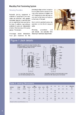
Figure 1 Jack details
NOTE If it is necessary to stress 75mm bars with a
stressing bridge L1 must be 320 long and the puller
is replaced by Bearing Plate and Nuts. /PULLER
25 - 50mm Bars (See above note) 75mm Bars and 25mm-50mm Bar in 200mm deep
Jack with stressing bridge and puller pockets jack with stressing stool and drawbar
Table 5: Jacking Dimensions
Max Min L1 L2 L3 L4 L5 L6 Min pocket
Jack type Weight load Bar dia. bar centres D.Dia S. Dia (min) dia.
3000 50 kgs 3000kN 75 170 250 187 135 330 - 865 1300 500 200
50 160 90 450
1000 26kgs 1000kN 40 120 176 125 75 301 385 564 850 300 135
36 116 65 370
32 114 60 360
450 15kgs 450kN 26.5 90 129 100 50 281 340 566 870 300 110
25 88 45 330
All jacks have 50mm stroke. All dimensions in mm
8