
Page 152 - Advanced Course
P. 152
KNX ADVANCED COURSE
3 Couplers for Powerline Installations
A KNX project can contain different communication media. The system devices for
coupling the various media are media couplers. For example, there is a media coupler for
linking a Powerline subsystem with a TP subsystem.
To keep the number of telegrams as low as possible in large KNX Powerline installations,
it is necessary to divide the installation up into several KNX areas. Each PL area receives
a unique system ID and is isolated from the total installation with band-stop filters. The
individual PL areas are interfaced via PL backbone couplers. These correspond to the
media coupler PL-TP in their structure and function but a data cable is connected instead
of the primary line. It has an internal power supply that can be used to power the TP side,
but an additional choke must then be used. The same specifications apply for the data
cable as for a TP backbone line.
Telegrams that cross different areas are routed selectively via the data cable to the
corresponding PL areas. At first different devices existed for the tasks of coupling
Powerline areas and media coupling. However, the two functionalities have meanwhile
been combined in one device called system coupler.
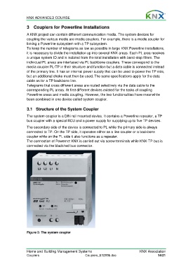
3.1 Structure of the System Coupler
The system coupler is a DIN rail mounted device. It contains a Powerline repeater, a TP
bus coupler with a special BCU and a power supply for supplying up to five TP devices.
The secondary side of the device is connected to PL while the primary side is always
connected to TP. On the TP side, it operates either as a line coupler or a backbone
coupler while on the PL side it also functions as a repeater.
The connection of Powernet KNX is carried out via screw terminals while KNX-TP bus is
connected via the black/red bus connector.
Figure 3: The system coupler
Home and Building Management Systems KNX Association
Couplers Couplers_E1209b.doc 14/21