
Page 154 - Advanced Course
P. 154
KNX ADVANCED COURSE
3.4 Commissioning of Devices
The data interface must always be inserted in the same medium as the device that is to
be programmed. It is currently not possible to commission devices across different media.
The following functions can however be carried out across media using ETS:
Switching the programming LED of the bus coupling unit or mains coupler ON/OFF
Reading the physical address (on the PL side, only one programming LED may be
switched on) - the system ID is not transmitted to the TP side
Sending group address
Reading device info
4 The IP Router
A further coupler between different media is the IP router. The IP router links KNX lines
together over data networks using the Internet protocol (IP). At the same time, this device
offers communication between KNX devices and PCs or other data processing devices
with an Ethernet connection.
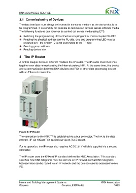
Figure 4: IP Router
The connection to the KNX TP is established via a bus connector. The link to the data
network (IP via 10BaseT) is carried out via an RJ45 socket.
For its operation, the IP router also requires AC/DC 24 V which is supplied via a second
connector.
The IP router uses the KNXnet/IP standard defined by KNX Association. This standard
specifies how KNX telegrams must be sent via an IP network so that KNX telegrams
between lines can be routed via an IP network and the bus can also be accessed from a
PC.
Home and Building Management Systems KNX Association
Couplers Couplers_E1209b.doc 16/21