
Page 180 - Advanced Course
P. 180
KNX ADVANCED COURSE
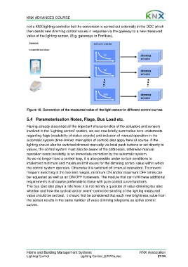
not a KNX lighting controller but the conversion is carried out externally in the DDC which
then sends new dimming control values in response via the gateway to a new measured
value of the lighting sensor. (E.g. gateways to Profibus).
Figure 16: Conversion of the measured value of the light sensor in different control curves
5.4 Parameterisation Notes, Flags, Bus Load etc.
Having already discussed all the important characteristics of the actuators and sensors
involved in the ‘Lighting control’ section, we can now briefly summarise here: statements
regarding flags (readability of status objects) and inclusion of manual operation in the
automatic system (time-limited interruption of control) also apply here of course. If the
lighting should also be switched/dimmed manually via local push buttons or set directly to
values, the control system must also be aware of the addresses, otherwise manual
operation leads inevitably to an immediate correction by the automatic system.
As we no longer have a control loop, it is also possible under certain conditions to
implement minimum and maximum limit values for the dimming control value within which
the control system operates. Otherwise it is switched off (manual operation). To prevent
frequent switching in the two limit ranges, minimum ON and/or maximum OFF times can
be requested as well as an ON/OFF hysteresis. The module that can fulfil these additional
requirements is of course preferable to those with pure control curve functions.
The bus load also plays a role here: it is not merely a question of value dimming but also
whether and how the cyclical and/or event–controlled sending of the lighting measured
value should be set best. It should first be considered that each new brightness value from
the sensor results in the same number of value dimming telegrams as active control
curves.
Home and Building Management Systems KNX Association
Lighting Control Lighting Control_E0310a.doc 21/34