
Page 181 - Advanced Course
P. 181
KNX ADVANCED COURSE
5.5 Parameterisation Example
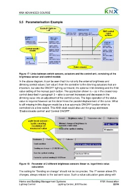
Figure 17: Links between switch sensors, actuators and the control unit, consisting of the
brightness sensor and control module
In the above diagram, it can be seen that it is not only the external brightness and
dimming control values (‘set value’) from the controller to the dimming actuators that are
important, but also the ON/OFF lighting command, the optional 4 bit dimming and the 8 bit
value setting of the manual push button. The application shown is – as in the closed-loop
control described in paragraph 3 – able to convert increases and decreases in the
dimming value into an adjustment of the control curves. The logic operation of the status
value is required however as this determines the parallel displacement of the curve. What
is still missing in this diagram would be a true automatic ON/OFF function which is
controlled via a time switch. This KNX clock would also use the group addresses
‘Enable/disable control’ and ‘Control ON/OFF’.
Figure 18: Parameter of 2 different brightness sensors: linear vs. logarithmic value
calculation
The setting for “Sending on change” should not be too precise. The 1 sensor allows 5%
st
changes, always related to the last sent value. Such a value calculation goes along with
Home and Building Management Systems KNX Association
Lighting Control Lighting Control_E0310a.doc 22/34