
Page 185 - Advanced Course
P. 185
KNX ADVANCED COURSE
6.3 Available Devices
Since the offset adjustment is derived from the dimming value of a regulated dimming
actuator, it would be possible for example to use the active status response (8 bit) of this
type of dimming actuator and simply add it to the established offset in a function module
or visualisation program. The newly specified control value would then be sent to the next
controlled light strip via another group address.
This procedure is however only advisable if the function module or visualisation program
mentioned are also available or if there is a cost benefit in using them compared to a
multi-layered lighting control system.
In terms of device implementation, it is much simpler in any case to use multi-channel
dimming actuators with an integrated sensor connection and controller application. It is
also possible here to configure internal offset connections between the actuator channels
so that fewer bus telegrams can be sent. This solution not only saves device addresses
but also costs in general.
6.4 Parameterisation Example
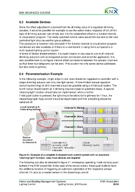
In the following example, 3 light strips in one room should be regulated or controller with a
single dimming actuator and only one light sensor. A time-limited manual operation
(switching/dimming) of all 3 channels should be possible using a 4-fold push button. The
fourth rocker should switch all 3 dimming channels back to automatic mode. A special
‘cleaning light’ function should also be implemented: when a further
1-fold push button is pressed, the light should be set to full brightness for 1 hour, the
closed-loop/open-loop control should be deactivated and then everything should be
switched off.
Figure 21: Example of a complete 3-channel room control system with an automatic
‘cleaning-light’ function: only 3 bus devices are required
The following can also be detected in figure 21: emergency operating mode via local push
buttons if the KNX should fail. In the case of the device shown, these push buttons have
the additional function of triggering an automatic calibration of the respective sensor
channel, if it acts as a master sensor in the closed-loop control.
Home and Building Management Systems KNX Association
Lighting Control Lighting Control_E0310a.doc 26/34