
Page 243 - Advanced Course
P. 243
KNX ADVANCED COURSE
4.2 Graphical Project Design in a Logic Diagram
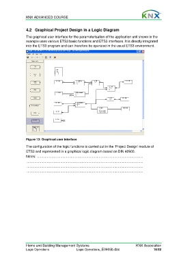
The graphical user interface for the parameterisation of the application unit shown in the
example uses various ETS3 basic functions and ETS3 interfaces. It is directly integrated
into the ETS3 program and can therefore be operated in the usual ETS3 environment.
Figure 13: Graphical user interface
The configuration of the logic functions is carried out in the ‘Project Design’ module of
ETS3 and represented in a graphical logic diagram based on DIN 40900.
Notes: ..............................................................................................................
.........................................................................................................................
.........................................................................................................................
.........................................................................................................................
Home and Building Management Systems KNX Association
Logic Operations Logic Operations_E0905b.doc 18/33