
Page 253 - Advanced Course
P. 253
KNX ADVANCED COURSE
6.1.2 OR Function (Disjunction) and OR Element (OR)
The sentence «If I inherit some money or win the lottery, I will travel round the world»
leads to an OR function. The world trip will be made if statement A (inheritance) or
statement B (lottery win) or both statements become true. You could argue whether the
trip would also be made if both statements come true. The grammatical mode of
expression is not precise enough here. For an OR function, the world trip would also have
to be made if A and B become true. The truth table in Diagram 2.3 indicates the
connection (‘1’ state = «true», ‘0’ state = «false»).
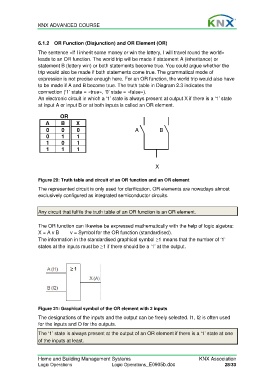
An electronic circuit in which a ‘1’ state is always present at output X if there is a ‘1’ state
at input A or input B or at both inputs is called an OR element.
OR
A B X
0 0 0 A B
0 1 1
1 0 1
1 1 1
X
Figure 20: Truth table and circuit of an OR function and an OR element
The represented circuit is only used for clarification. OR elements are nowadays almost
exclusively configured as integrated semiconductor circuits.
Any circuit that fulfils the truth table of an OR function is an OR element.
The OR function can likewise be expressed mathematically with the help of logic algebra:
X = A v B v = Symbol for the OR function (standardised).
The information in the standardised graphical symbol ≥1 means that the number of ‘1’
states at the inputs must be ≥1 if there should be a ‘1’ at the output.
Figure 21: Graphical symbol of the OR element with 2 inputs
The designations of the inputs and the output can be freely selected. I1, I2 is often used
for the inputs and O for the outputs.
The ‘1’ state is always present at the output of an OR element if there is a ‘1’ state at one
of the inputs at least.
Home and Building Management Systems KNX Association
Logic Operations Logic Operations_E0905b.doc 28/33