
Page 255 - Advanced Course
P. 255
KNX ADVANCED COURSE
6.2 Compound Elements
6.2.1 NAND Element (NAND)
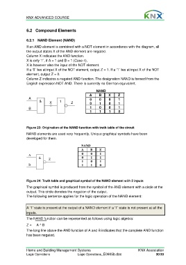
If an AND element is combined with a NOT element in accordance with the diagram, all
the output states X of the AND element are negated.
Column X indicates the AND function.
X is only ‘1’, if A = 1 and B = 1 (Case 4).
X is however also the input of the NOT element.
If a ‘0’ lies at input X of the NOT element, output Z = 1. If a ‘1’ lies at input X of the NOT
element, output Z = 0.
Column Z indicates a negated AND function. The designation NAND is formed from the
English expression NOT AND. There is currently no German equivalent.
NAND
A B X Z
A 0 0 0 1
& X 1 Z 0 1 0 1
B 1 0 0 1
1 1 1 0
Figure 23: Origination of the NAND function with truth table of the circuit
NAND elements are used very frequently. Unique graphical symbols have been
developed for them.
NAND
A B Z
A 0 0 1
& Z 0 1 1
1 0 1
B 1 1 0
Figure 24: Truth table and graphical symbol of the NAND element with 2 inputs
The graphical symbol is produced from the symbol of the AND element with a circle at the
output. This circle denotes the negation of the output.
The following sentence applies for the logic operation of the NAND element:
A ‘1’ state is present at the output of a NAND element if a ‘1’ state is not present at all the
inputs.
The NAND function can be represented as follows using logic algebra:
Z = A ^ B
The long line above the AND function of A and B indicates that the complete AND function
has been negated.
Home and Building Management Systems KNX Association
Logic Operations Logic Operations_E0905b.doc 30/33