
Page 256 - Advanced Course
P. 256
KNX ADVANCED COURSE
6.2.2 NOR Element (NOR)
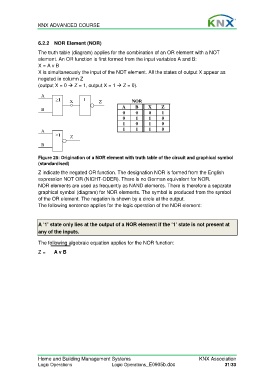
The truth table (diagram) applies for the combination of an OR element with a NOT
element. An OR function is first formed from the input variables A and B:
X = A v B
X is simultaneously the input of the NOT element. All the states of output X appear as
negated in column Z
(output X = 0 Z = 1, output X = 1 Z = 0).
A
≥1 X 1 Z NOR
B A B X Z
0 0 0 1
0 1 1 0
1 0 1 0
A 1 1 1 0
≥1 Z
B
Figure 25: Origination of a NOR element with truth table of the circuit and graphical symbol
(standardised)
Z indicate the negated OR function. The designation NOR is formed from the English
expression NOT OR (NICHT-ODER). There is no German equivalent for NOR.
NOR elements are used as frequently as NAND elements. There is therefore a separate
graphical symbol (diagram) for NOR elements. The symbol is produced from the symbol
of the OR element. The negation is shown by a circle at the output.
The following sentence applies for the logic operation of the NOR element:
A ‘1’ state only lies at the output of a NOR element if the ‘1’ state is not present at
any of the inputs.
The following algebraic equation applies for the NOR function:
Z = A v B
Home and Building Management Systems KNX Association
Logic Operations Logic Operations_E0905b.doc 31/33