
Page 252 - Advanced Course
P. 252
KNX ADVANCED COURSE
6 Logic Operations (Appendix)
6.1 Basic Functions and Elements
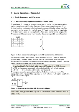
6.1.1 AND Function (Conjunction) and AND Element (AND)
The sentence «If the weather is nice tomorrow and my brother has time, we are going
sailing» contains an AND function. Statement A (nice weather) and statement B (my
brother has time) must apply i.e. be true to make statement X (going sailing) true. This
connection can be represented in a truth table. A ‘1’ state means «true» or «applicable».
A ‘0’ state means «false» or «not applicable». Four cases (combinations) are possible.
The cases can follow any order in principle but should correspond to a specific pattern.
(AND)
A B X A
0 0 0
0 1 0
1 0 0
1 1 1 B
X
Figure 18: Truth table and circuit diagram of an AND function and an AND element
An electronic circuit in which only a ‘1’ state is present at output X when ‘1’ states are
present at input A and at input B, is called AND, an AND element or an AND gate.
An AND element can be implemented by a circuit diagram. Nowadays however integrated
semiconductor circuits are used almost exclusively.
Any circuit that fulfils the truth table of an AND function is an AND element.
The AND function can be expressed mathematically with the help of logic algebra:
X = A ^ B ^ Symbol for the AND function (standardised).
The diagram shows the graphical symbol of an AND element with two inputs. The
designations of the inputs and the output can be freely selected. I1, I2 is often used for the
inputs and O for the outputs.
A (I1)
& X
B (I2) (A)
Figure 19: Graphical symbol of the AND element with 2 inputs
The ‘1’ state is only present at the output of an AND element if there is also a ‘1’ state at
all the inputs.
Home and Building Management Systems KNX Association
Logic Operations Logic Operations_E0905b.doc 27/33