
Page 110 - Digital Electronics by harish
P. 110
When R/ line is LOW, input buffer is enabled and output buffer is disabled. When
R/ line is HIGH, input buffer is disabled and output buffer is enabled.
Write operation:
1. By making the R/ line LOW, the input buffer is enabled and the output buffer is
disabled.
2. To write a „1‟
a. DIN line is made HIGH.
b. ROW Select is made HIGH and the transistor is turned ON.
c. Now, the capacitor is charged and stores a „1‟.
3. To write a „0‟
a. DIN line is made LOW.
b. ROW Select is made HIGH and the transistor is turned ON.
c. Now, the capacitor is discharged and stores a „0‟.
4. When the ROW Select is made LOW, the transistor is switched OFF and the charge on
the capacitor is not disturbed.
Read operation:
1. By making the R/ line HIGH, the output buffer is enabled and input buffer is disabled.
2. ROW Select line is made HIGH. This turns ON the transistor and connects the capacitor
to the DOUT line through the output buffer.
Refresh operation:
1. To enable the Refresh operation, R/ line, ROW line and REFRESH line are made
HIGH.
2. The transistor is turned ON and the capacitor is connected to COLUMN line.
3. As R/ is HIGH, the output buffer is enabled and the stored data bit is applied to the
input of the refresh buffer.
4. The output of the refresh buffer either „0‟ or „1‟ is applied to the COLUMN line and this
maintains the charge on the capacitor.
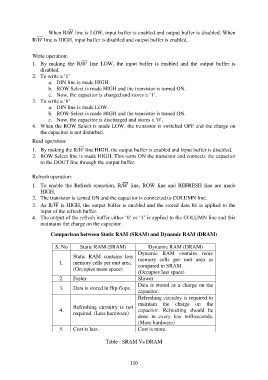
Comparison between Static RAM (SRAM) and Dynamic RAM (DRAM)
S. No Static RAM (SRAM) Dynamic RAM (DRAM)
Dynamic RAM contains more
Static RAM contains less
1. memory cells per unit area. memory cells per unit area as
compared to SRAM.
(Occupies more space)
(Occupies less space)
2. Faster Slower
Data is stored as a charge on the
3. Data is stored in flip-flops.
capacitor.
Refreshing circuitry is required to
maintain the charge on the
Refreshing circuitry is not
4. capacitor. Refreshing should be
required. (Less hardware)
done in every few milliseconds.
(More hardware)
5. Cost is less. Cost is more.
Table : SRAM Vs DRAM
110