
Page 108 - Digital Electronics by harish
P. 108
The Bipolar Static RAM cell is implemented using two BJTs with multiple emitters.
The two transistors are cross-coupled together to get the bi-stable multi-vibrator (flip-flop)
operation. Large number of similar cells is connected in matrix form. The X-select (ROW
select) line and Y-select (COLUMN select) line are used to select a particular cell from the
matrix.The Set input is used to store a „1‟ in the memory cell and Reset input is used to store
a „0‟ in the memory cell. The output is taken either from Data line or from line. The Q1
and Q2 are cross coupled inverters, hence one is always OFF while the other is ON.
Read operation: When the cell is selected by the X-select and Y-select lines, the data stored
in the cell is available at Data and output lines.
Write operation: The cell is selected by the X-select and Y-select lines. By pulsing a HIGH
on the SET input line, a „1‟ is stored in the cell. Similarly, by pulsing a HIGH in the RESET
input line, a „1‟ is stored in the cell.
4.3.2 MOS Static RAM Cell
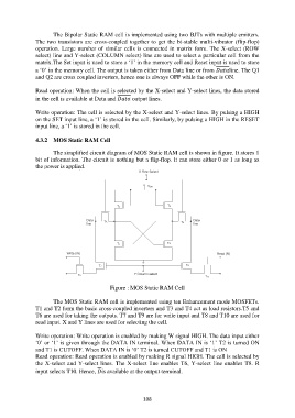
The simplified circuit diagram of MOS Static RAM cell is shown in figure. It stores 1
bit of information. The circuit is nothing but a flip-flop. It can store either 0 or 1 as long as
the power is applied.
Figure : MOS Static RAM Cell
The MOS Static RAM cell is implemented using ten Enhancement mode MOSFETs.
T1 and T2 form the basic cross-coupled inverters and T3 and T4 act as load resistors.T5 and
T6 are used for taking the outputs. T7 and T9 are for write input and T8 and T10 are used for
read input. X and Y lines are used for selecting the cell.
Write operation: Write operation is enabled by making W signal HIGH. The data input either
„0‟ or „1‟ is given through the DATA IN terminal. When DATA IN is „1‟ T2 is turned ON
and T1 is CUTOFF. When DATA IN is „0‟ T2 is turned CUTOFF and T1 is ON
Read operation: Read operation is enabled by making R signal HIGH. The cell is selected by
the X-select and Y-select lines. The X-select line enables T6, Y-select line enables T8. R
input selects T10. Hence, is available at the output terminal.
108