
Page 29 - Digital Electronics by harish
P. 29
1.4 LOGIC GATES
1.4.1 Logic gates
A gate is a logic circuit with one output and one or more inputs. The output signal occurs
only for certain input combinations. The input and output signals are digital in nature ie.
either 0 (low) or 1 (high). All the possible input combinations and their corresponding output
conditions are noted in a table, called truth table.
In digital systems, two different voltage levels (0v and 5v) are used to represent the logic
levels „0‟ and „1‟. If the high voltage level (5v) represents logic „1‟ and low voltage level (0v)
represents logic „0‟, then the system is called positive logic. But some systems use the low
voltage level (0v) for logic „1‟ and the high voltage level (5v) for logic „0‟. This is called
negative logic. This is shown in the following figure.
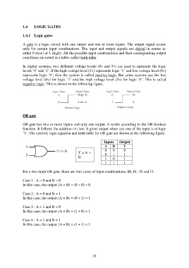
OR gate
OR gate has two or more inputs and only one output. It works according to the OR boolean
function. It follows the addition (+) law. It gives output when any one of the input is at logic
„1‟. The symbol, logic equation and truth table for OR gate are shown in the following figure.
Inputs Output
A B Y
0 0 0
Y = A + 0 1 1
B 1 0 1
1 1 1
For a two input OR gate, there are four cases of input combinations, 00, 01, 10 and 11.
Case 1 : A = 0 and B = 0
In this case, the output (A + B) = (0 + 0) = 0
Case 2 : A = 0 and B = 1
In this case, the output (A + B) = (0 + 1) = 1
Case 3 : A = 1 and B = 0
In this case, the output (A + B) = (1 + 0) = 1
Case 4 : A = 1 and B = 1
In this case, the output (A + B) = (1 + 1) = 1
29