
Page 30 - Digital Electronics by harish
P. 30
For a three input OR gate, there are eight input combinations, 000, 001, 010, 011, 100, 101,
n
110 and 111. The generalized formula for the number of input combinations is 2 , where „n‟
is the number of inputs in the gate.
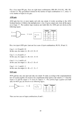
AND gate
AND gate has two or more inputs and only one output. It works according to the AND
boolean function. It follows the multiplication (.) law. It gives output only when all the inputs
are at logic „1‟. The symbol, logic equation and truth table for AND gate are shown in the
following figure.
Inputs Output
A B Y
Y = A . 0 0 0
B 0 1 0
1 0 0
1 1 1
For a two input AND gate, there are four cases of input combinations, 00, 01, 10 and 11.
Case 1 : A = 0 and B = 0
In this case, the output (A . B) = (0 . 0) = 0
Case 2 : A = 0 and B = 1
In this case, the output (A . B) = (0 . 1) = 0
Case 3 : A = 1 and B = 0
In this case, the output (A . B) = (1 . 0) = 0
Case 4 : A = 1 and B = 1
In this case, the output (A . B) = (1 . 1) = 1
NOT gate
NOT gate has only one input and only one output. It works according to the complementation
law of boolean algebra. Its output is the complement of the input ie. the output is „1‟ when the
input is „0‟ and the output is „0‟ when the input is „1‟. The symbol, logic equation and truth
table for NOT gate are shown in the following figure.
Input Output
Y = A A Y
0 1
1 0
There are two cases of input combinations, 0 and 1.
30