
Page 31 - Digital Electronics by harish
P. 31
Case 1 : A = 0
In this case, the output () = (0) = 1
Case 2 : A = 1
In this case, the output () = (1) = 0
The other names of NOT gate are Inverter gate and Complement gate.
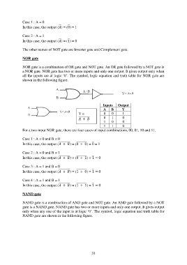
NOR gate
NOR gate is a combination of OR gate and NOT gate. An OR gate followed by a NOT gate is
a NOR gate. NOR gate has two or more inputs and only one output. It gives output only when
all the inputs are at logic „0‟. The symbol, logic equation and truth table for NOR gate are
shown in the following figure.
Inputs Output
A B Y
Y = 0 0 1
+ 0 1 0
1 0 0
1 1 0
For a two input NOR gate, there are four cases of input combinations, 00, 01, 10 and 11.
Case 1 : A = 0 and B = 0
In this case, the output ( + ) = (0 + 0) = 0 = 1
Case 2 : A = 0 and B = 1
In this case, the output ( + ) = (0 + 1) = 1 = 0
Case 3 : A = 1 and B = 0
In this case, the output ( + ) = (1 + 0) = 1 = 0
Case 4 : A = 1 and B = 1
In this case, the output ( + ) = (1 + 1) = 1 = 0
NAND gate
NAND gate is a combination of AND gate and NOT gate. An AND gate followed by a NOT
gate is a NAND gate. NAND gate has two or more inputs and only one output. It gives output
only when any one of the input is at logic „0‟. The symbol, logic equation and truth table for
NAND gate are shown in the following figure.
31