
Page 32 - Digital Electronics by harish
P. 32
Inputs Output
A B Y
0 0 1
Y = . 0 1 1
1 0 1
1 1 0
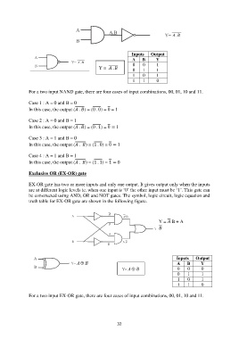
For a two input NAND gate, there are four cases of input combinations, 00, 01, 10 and 11.
Case 1 : A = 0 and B = 0
In this case, the output ( . ) = (0 . 0) = 0 = 1
Case 2 : A = 0 and B = 1
In this case, the output ( . ) = (0 . 1) = 0 = 1
Case 3 : A = 1 and B = 0
In this case, the output ( . ) = (1 . 0) = 0 = 1
Case 4 : A = 1 and B = 1
In this case, the output ( . ) = (1 . 1) = 1 = 0
Exclusive OR (EX-OR) gate
EX-OR gate has two or more inputs and only one output. It gives output only when the inputs
are at different logic levels ie. when one input is „0‟ the other input must be „1‟. This gate can
be constructed using AND, OR and NOT gates. The symbol, logic circuit, logic equation and
truth table for EX-OR gate are shown in the following figure.
Y = B + A
Inputs Output
A B Y
0 0 0
0
1
1
1 0 1
1 1 0
For a two input EX-OR gate, there are four cases of input combinations, 00, 01, 10 and 11.
32