
Page 70 - Digital Electronics by harish
P. 70
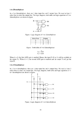
1-to-2Demultiplexer

               In a 1-to-2demultiplexer, there are 1 data input line and 2 output lines. We need at least 1
               select line to select the output line. The logic diagram, truth table and logic equations of 1-to-
               2demultiplexer are shown in figure.


                                      Figure : Logic diagram of 1-to-2demultiplexer

                                                Select lines    Outputs
                                                     A          Y 1    Y 0
                                                     0          0      D
                                                     1          D      0

                                        Figure : Truth table of 1-to-2demultiplexer

                                                        Y 0 =  D
                                                        Y 1 = A D

               When A = 0, the first AND gate is enabled. Hence, the input D (0 or 1) will be available at
               the output Y 0. When A = 1, the second AND gate is enabled and the output Y 1will get the
               input D.

               1-to-4 Demultiplexer

               In a 1-to-4 demultiplexer, there are 1 data input line and 4 output lines. We need at least 2
               select lines to select the output line. The logic diagram, truth table and logic equations of 1-
               to-4 demultiplexer are shown in figure.


                                      Figure : Logic diagram of 1-to-4 demultiplexer


                                                           70