
Page 393 - CarrLaneCatalog_2019ed-c.pdf
P. 393
LOCATING AND CLAMPING PRINCIPLES
CONTINUED FROM PREVIOUS PAGE
jaw holds the workpiece against the solid jaw and maintains the
position of the part during the cut.
LOCATING GUIDELINES
No single form or type of locator will work for every workholder,
and each locator must be carefully planned into the design.
Positioning Locators
The primary function of any locator is to reference the workpiece
and to ensure repeatability. Locators must be properly positioned
relative to both the workholder and to the workpiece.
• When practical, position locators to contact the workpiece on a
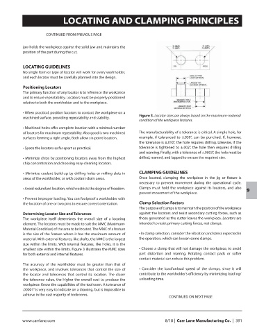
Figure 3. Locator sizes are always based on the maximum-material
machined surface, providing repeatability and stability.
condition of the workpiece features.
• Machined holes offer complete location with a minimal number
of locators for maximum repeatability. Also good is two machined The manufacturability of a tolerance is critical. A simple hole, for
surfaces forming a right angle. Both allow six-point location. example, if toleranced to ±.050”, can be punched. If, however,
the tolerance is ±.010”, the hole requires drilling. Likewise, if the
• Space the locators as far apart as practical. tolerance is tightened to ±.002”, the hole then requires drilling
and reaming. Finally, with a tolerance of ±.0003”, the hole must be
• Minimize chips by positioning locators away from the highest drilled, reamed, and lapped to ensure the required size.
chip concentration and choosing easy-cleaning locators.
• Minimize coolant build-up by drilling holes or milling slots in CLAMPING GUIDELINES
areas of the workholder, or with coolant-drain areas. Once located, clamping the workpiece in the jig or fixture is
necessary to prevent movement during the operational cycle.
• Avoid redundant location, which restricts the degree of freedom. Clamps must hold the workpiece against its locators, and also
prevent movement of the workpiece. 9
• Prevent improper loading. You can foolproof a workholder with
the location of one or two pins to ensure correct orientation. Clamp Selection Factors
The purpose of clamps is to maintain the position of the workpiece
Determining Locator Size and Tolerances against the locators and resist secondary cutting forces, such as
The workpiece itself determines the overall size of a locating those generated as the cutter leaves the workpiece. Locators are
element. The locators must be made to suit the MMC (Maximum- intended to resist primary cutting forces, not clamps.
Material Condition) of the area to be located. The MMC of a feature
is the size of the feature where it has the maximum amount of • In clamp selection, consider the vibration and stress expected in
material. With external features, like shafts, the MMC is the largest the operation, which can loosen some clamps.
size within the limits. With internal features, like holes, it is the
smallest size within the limits. Figure 3 illustrates the MMC sizes • Choose a clamp that will not damage the workpiece, to avoid
for both external and internal features. part distortion and marring. Rotating contact pads or softer
contact material can reduce this problem.
The accuracy of the workholder must be greater than that of
the workpiece, and involves tolerances that control the size of • Consider the load/unload speed of the clamps, since it will
the locator and tolerances that control its location. The closer contribute to the workholder’s efficiency by minimizing loading/
the tolerance value, the higher the overall cost to produce the unloading time.
workpiece. Know the capabilities of the toolroom. A tolerance of
.00001” is very easy to indicate on a drawing, but is impossible to
achieve in the vast majority of toolrooms.
CONTINUED ON NEXT PAGE
www.carrlane.com 8/18 | Carr Lane Manufacturing Co. | 391