
Page 625 - CarrLaneCatalog_2019ed-c.pdf
P. 625
Design Information
F X = 0
= -1800 + R 1 + (.19)(1500 + F R )
F y = 0
= R 2 - 1500 - F R
M = 0
= (34)(1800) - (15)(1500) - (30)(F R )
Friction Friction
Contact surfaces coefficent coefficent Solving for the variables,
(Dry) (Lubricated) F R = 1290 lbs
Steel on steel .15 .12 R 1 = 1270 lbs
Steel on cast iron .19 .10 R 2 = 2790 lbs
Cast iron on cast iron .30 .19 In other words, the combined force from all
clamps on the right side must be greater
Intuitively, force direction is virtually all than 1290 lbs. We recommend a 2-to-1
horizontal. In this example (negligible z-axis (frictional force resists the entire cutting force). safety factor (2580 lbs). Even though F L (the
component). Direction varies between the x With workpiece stops and multi-direction combined force from all clamps on the left
and y axes as the cut progresses. forces, calculations become much more side) equals zero, a small clamping force may
complicated. To simplify somewhat, determine be desirable to prevent vibration. Too much
the worst-case force situation intuitively, then
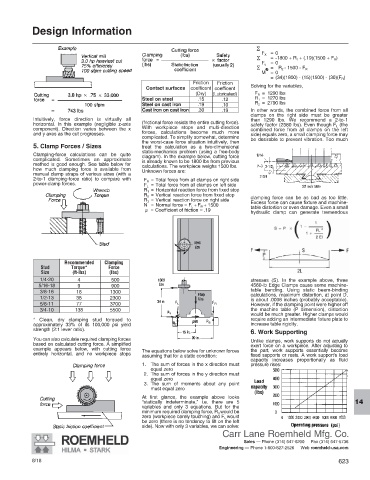
5. Clamp Forces / Sizes treat the calculation as a two-dimensional
static-mechanics problem (using a free-body
Clamping-force calculations can be quite diagram). In the example below, cutting force
complicated. Sometimes an approximate is already known to be 1800 lbs from previous
method is good enough. See table below for calculations. The workpiece weighs 1500 lbs.
how much clamping force is available from Unknown forces are:
manual clamp straps of various sizes (with a
2-to-1 clamping-force ratio) to compare with F R = Total force from all clamps on right side
power-clamp forces. F L = Total force from all clamps on left side
R 1 = Horizontal reaction force from fixed stop
R 2 = Vertical reaction force from fixed stop clamping force can be as bad as too little.
R 3 = Vertical reaction force on right side Excess force can cause fixture and machine-
N = Normal force = F L + F R + 1500 table distortion or even damage. Even a small
μ = Coefficient of friction = .19
hydraulic clamp can generate tremendous
Recommended Clamping
Stud Torque* Force
Size (ft-lbs) (lbs)
1/4-20 4 500 stresses (S). In the example above, three
5/16-18 9 900 4560-lb Edge Clamps cause some machine-
3/8-16 16 1300 table bending. Using static beam-binding
calculations, maximum distortion, at point D,
1/2-13 38 2300 is about .0006 inches (probably acceptable).
5/8-11 77 3700 However, if the clamping point were higher off
3/4-10 138 5500 the machine table (P dimension), distortion
would be much greater. Higher clamps would
* Clean, dry clamping stud torqued to require adding an intermediate fixture plate to
approximately 33% of its 100,000 psi yield increase table rigidity.
strength (2:1 lever ratio).
6. Work Supporting
You can also calculate required clamping forces Unlike clamps, work supports do not actually
based on calculated cutting force. A simplified exert force on a workpiece. After adjusting to
example appears below, with cutting force The equations below solve for unknown forces the part, work supports essentially become
entirely horizontal, and no workpiece stops
assuming that for a static condition: fixed supports or rests. A work support’s load
capacity increases proportionally as fluid
1. The sum of forces in the x direction must pressure rises:
equal zero
2. The sum of forces in the y direction must
equal zero
3. The sum of moments about any point
must equal zero
At first glance, the example above looks
“statically indeterminate,” i.e. there are 5
14
variables and only 3 equations. But for the
minimum required clamping force, R 3 would be
zero (workpiece barely touching) and F L would
be zero (there is no tendency to lift on the left
side). Now with only 3 variables, we can solve:
Carr Lane Roemheld Mfg. Co.
Sales — Phone (314) 647-6200 Fax (314) 647-5736
Engineering — Phone 1-800-827-2526 Web roemheld-usa.com
8/18 623