
Page 628 - CarrLaneCatalog_2019ed-c.pdf
P. 628
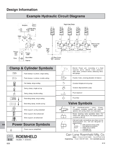
Design Information


                             Example Hydraulic Circuit Diagrams


           Clamp & Cylinder Symbols                                           Electric Power unit, consisting of a fluid
                                                                              reservoir, pump, electric motor, pressure-
                                                                              relief valve, pressure switch, clamping valve,
                             Push clamp or cylinder, single acting            and gauge.


                           Push clamp or cylinder, double acting              Electric motor, showing direction of rotation

                             Pull clamp, single acting                        Constant displacement pump

                                                                              Variable displacement pump
                             Swing clamp, single acting
                                                                              Fluid reservoir
                             Swing clamp, double acting
                                                                              Fluid filter
                             Extending clamp, single acting

                                                                          Valve Symbols
                             Extending clamp, double acting
                                                                              3/2  directional-control  valve  (3-way,
                                                                              2-position), complete symbol with solenoid
                             Work support, spring extended
                                                                              operator and spring return (normally open)
                             Work support, fluid advanced                     Boxes showing valve positions (two). For
                                                                              valves with spring return, the neutral position
                             Work support, air advanced                       is shown at left (0).
                                                                              Inlet and outlet connections are drawn at the
                                                                              neutral-position box, and are designed by
              Power Source Symbols                                            capital letters:
                                                                                      =  Inlet pressure from pump
                                                                                P
   14
                                                                               A,B,C... =  Operating connections
                                                                                R,S,T   =  Outlet return (tank)
                           Power source (simplified)                           L      =  Leakage line
                                                                               Z,Y,Z   =  Control Lines
                                                                       Carr Lane Roemheld Mfg. Co.
                                                                              Sales — Phone (314) 647-6200     Fax (314) 647-5736
                                                                      Engineering — Phone 1-800-827-2526     Web roemheld-usa.com

        626                                                                                                  8/18