
Page 626 - CarrLaneCatalog_2019ed-c.pdf
P. 626
Design Information
Choose enough load capacity to resist:
(1) ma chining forces; (2) workpiece weight; (3)
clamping forces not resisted by fixed stops.
3. Machine-tool interlock. In automated
systems where timing and synchronization are via hose, tubing, or drilled passages. When
important, double-acting clamps are the best hydraulic pressure acts on a clamp’s piston
When supporting underneath a clamp, as choice. By installing pressure switches in both area, it generates external force according
in the example above, load capacity should clamping and return lines, a machine controller to the physical relationship F=P x A:
be substantially greater than clamping knows exact clamp status at all times.
force. Not only must the support resist static
clamping force, it must resist dynamic load 8. Clamping Time
too (the “hammering” due to clamping-arm Hydraulic clamping is usually fast, but not
mo men tum). We recommend a load capacity instantaneous. To estimate clamping time,
of at least 2 times the clamping force. Another consider the two phases of clamping:
factor when clamping over a work support is 1. Extending time, under low-pressure
that the clamp may build up force faster than free flow
the support builds up load capacity. To avoid 2. Pressure-building time
this, use a sequence valve to delay clamping
until load capacity builds up.
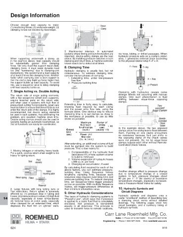
7. Single Acting vs. Double Acting Clamping with hydraulics causes some
The return side of single acting elements, strange effects not occurring with manual
with a few exceptions (small work supports), clamps. One such phenomenon is fluid
require breather ports on the return side, shifting between equal-force opposing
and when used in systems with high flow or clamps.
pressurized cutting fluids/coolants, great care Extending time is fairly easy to calculate,
must be taken to ensure that these fluids do not knowing fluid required by each clamp
enter the return side of the clamps. It is highly and the power units flow rate, using the
recommended that double acting elements formula below. One obvious way to reduce
be used in such systems, thus eliminating the clamping time is to set clamps as close to
problem, and resultant machine down time. the workpiece at possible, to use as little
Double acting clamps should also be used in stroke as possible.
systems having an automatic load/unload, so
that all functions can easily be coordinated.
In the example above, the two opposed
clamps allow the workpiece to float between
them. Pushing on one clamp encounters
no resistance because fluid just shifts to
the opposing clamp (if the check valves
were not present). Do not let equal-force
clamps oppose each other without Remote-
After extending, an additional volume of fluid Controlled Check Valves.
must be pumped into the system to build
pressure. This is due mainly to:
1. Moving linkages or retracting heavy loads.
For a quick, positive return when weight is too 1. Compressibility of the hydraulic fluid
heavy for spring return. (add about 4% of total system volume
to build to 7250 psi)
2. Volume expansion of hydraulic hoses
(.066 cu.in. per foot)
3. Charging an accumulator, if used
By calculating fluid required for each of the
above factors, you can estimate pressure-
building time. Using Sequence Valves Another strange effect is pressure change
lengthens clamping time, because each due to temperature change of a closed
sequence step requires extending time and system. In fact, pressure changes about
pressure-building time. To reduce clamping 80 psi per 1° F! Be careful of excessive
time, set Sequence-Valve trigger pressure temperature changes, especially increases.
as low as possible. With multiple Sequence Use a Pressure-Relief Valve for safety.
Valves, set trigger-pressure differences at
2. Large fixtures with long tubing runs or their minimum allowables value. 10. Hydraulic Symbols and
flow restrictions. Return speed is adversely Circuit Diagrams
affected by: (1) pressure drop in tubing and 9. Other Hydraulic Considerations
hoses; (2) pressure drop in valves; (3) high fluid The basis of hydraulic clamping systems is Hydraulic symbols and diagrams area a
viscosity, especially at lower temperatures; “Pascal’s Law”, which says that if pressure useful “shorthand” method of describing how
14
(4) frictional force at piston seals, especially is applied to a static fluid that is completely a clamping circuit works without detailed
when clamped for an extended time, which enclosed, that pressure is transmitted drawings. The following pages show two
displaces the fluid film on cylinder walls. equally in all directions: This principle is circuit examples, and a summary listing of
used to transmit force to remote locations, hydraulic symbols.
Carr Lane Roemheld Mfg. Co.
Sales — Phone (314) 647-6200 Fax (314) 647-5736
Engineering — Phone 1-800-827-2526 Web roemheld-usa.com
624 8/18