
Page 192 - Robot Design Handbook ROBOCON Malaysia 2019
P. 192
2.2.1 The MR1 Main Board
(a) (b)
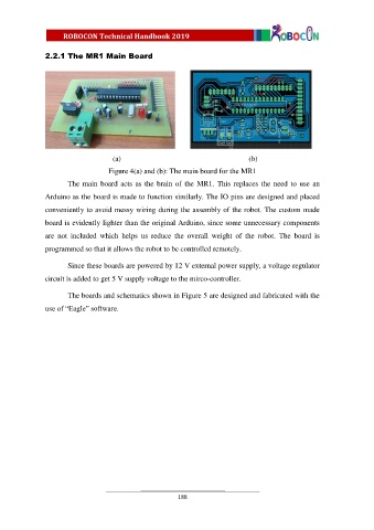
Figure 4(a) and (b): The main board for the MR1
The main board acts as the brain of the MR1. This replaces the need to use an
Arduino as the board is made to function similarly. The IO pins are designed and placed
conveniently to avoid messy wiring during the assembly of the robot. The custom made
board is evidently lighter than the original Arduino, since some unnecessary components
are not included which helps us reduce the overall weight of the robot. The board is
programmed so that it allows the robot to be controlled remotely.
Since these boards are powered by 12 V external power supply, a voltage regulator
circuit is added to get 5 V supply voltage to the mirco-controller.
The boards and schematics shown in Figure 5 are designed and fabricated with the
use of “Eagle” software.
188