
Page 214 - Robot Design Handbook ROBOCON Malaysia 2019
P. 214
3.0 PRESENTATION OF DATA
3.1 Manual Robot
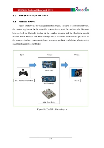
Figure 10 shows the block diagram for this project. The input is a wireless controller,
the custom application in the controller communicates with the Arduino via Bluetooth
between built-in Bluetooth module in the wireless joystick and the Bluetooth module
attached to the Arduino. The Arduino Mega acts as the micro-controller that processes all
the input received and gives output signals as programmed to the solid-state relay to switch
on/off the Electric Scooter Motor.
Figure 10: The MR1 block diagram
210