Page 242 - Robot Design Handbook ROBOCON Malaysia 2019
P. 242

1.  Cylinder for pneumatic hand
                   2.  Pneumatic hand
                   3.  Motor
                   4.  Omni-wheel
                   5.  Cylinder for the Shagai launcher
                   6.  Cylinder for the Gerege clamper


                                         Figure 4: A closer look at omni wheel


                                    Figure 5: A closer look at clamper of the Gerege

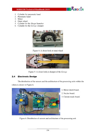
               2.4    Electronic Design


                       The distribution of the sensors and the architecture of the processing units within the
               robots is shown in Figure 6.


                                                                            1. Motor shield board.

                                                                            2. Nucleo board.
                                                                            3. Custom made board.


                         Figure 6: Distribution of sensors and architecture of the processing unit


                                                          238
   237   238   239   240   241   242   243   244   245   246   247