
Page 246 - Robot Design Handbook ROBOCON Malaysia 2019
P. 246
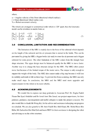
where,
               ω = Angular velocity of the Omni-directional wheel (rad/sec).
               r = Omni-directional wheel radius (cm).
               Vθ = Robot movement velocity.

               The wheels are arranged in symmetrical order which is 120° apart, thus the kinematic
               model can be rewritten in matrix form as:

                         −1/2     −1/2      1         1
               [       ] = [√3/2  −√3/2     0 ] [   ]                                                  (7)
                                                    2
                          1/       1/      1/         3


               3.0     CONCLUSION, LIMITATION AND RECOMMENDATION


                       The limitation of the MR1 is mainly due to the force of the solenoid which depends
               on the length of the solenoid and the air pressure that is stored in the bottle. This can be

               prevented by giving the MR1 a bigger bottle (air-tank) to store the air pressure and a bigger
               solenoid for extra power. The other limitation of the MR1 comes from the triangle base

               shape structure. The upper design must be balanced equally for the MR1 to move faster.

               Another way is to change the base structure design for the MR1. The MR2 robot cannot
               move fast because of the limited torque of the motor servo. The torque is only enough to

               support the weight of the body. The MR2 also cannot make a big step because it will lose
               its stability and tends to fall on three legs. To prevent this from occurring, the MR2 can only

               make  small  steps.  In  conclusion,  the  MR1  and  the  MR2  need  more  upgrades  and

               improvements for the robots to be more reliable.


               4.0     ACKNOWLEDGMENTS

                       We would like to express our deep gratitude to Associate Prof. Dr. Engku Fadzli
               Hasan Bin Syed Abdullah and Dr Azrul Amri Bin Jamal, our project supervisors, for their

               patience, guidance, encouragement and useful critiques to make this project a success. We
               also would like to thank Mr Weng Kit, for his advice and assistance in keeping our progress

               on schedule. We are also grateful to Mr Amir Fadzli Bin Abd Ghani, Mr. Mohd Hosni Bin
               Rifin, Mr Zarkashim Bin Mad Zali and team FRIT for their assistance in designing the robot

               and advising us on the robot structure.


                                                          242