
Page 322 - Robot Design Handbook ROBOCON Malaysia 2019
P. 322
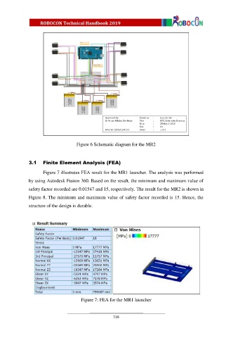
Figure 6 Schematic diagram for the MR2


               3.1    Finite Element Analysis (FEA)

                       Figure 7 illustrates FEA result for the MR1 launcher. The analysis was performed
               by using Autodesk Fusion 360. Based on the result, the minimum and maximum value of

               safety factor recorded are 0.01547 and 15, respectively. The result for the MR2 is shown in

               Figure 8. The minimum and maximum value of safety factor recorded is 15. Hence, the
               structure of the design is durable.


                                          Figure 7: FEA for the MR1 launcher


                                                          318