
Page 62 - Robot Design Handbook ROBOCON Malaysia 2019
P. 62
(c)
(a) (b) (d)
(e)
(f) (g) (h) (i)
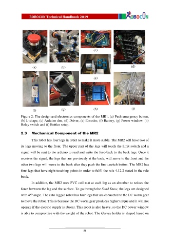
Figure 2: The design and electronics components of the MR1. (a) Push emergency button,
(b) L-shape, (c) Arduino due, (d) Driver, (e) Encoder, (f) Battery, (g) Power window, (h)
Relay switch and (i) Bottles setup.
2.3 Mechanical Component of the MR2
This robot has four legs in order to make it more stable. The MR2 will have two of
its legs moving to the front. The upper part of the legs will touch the limit switch and a
signal will be sent to the arduino to read and write the feed-back to the back legs. Once it
receives the signal, the legs that are previously at the back, will move to the front and the
other two legs will move to the back after they push the limit switch button. The MR2 has
four legs that have eight touching points in order to fulfil the rule 4.12.2 stated in the rule
book.
In addition, the MR2 uses PVC coil mat at each leg as an absorber to reduce the
force between the leg and the surface. To go through the Sand Dune, the legs are designed
with 45º angle. The auto legged robot has four legs that are connected to the DC worm gear
to move the robot. This is because the DC worm gear produces higher torque and it will not
operate if the electric supply is absent. This robot is also heavy, so the DC power window
is able to compromise with the weight of the robot. The Gerege holder is shaped based on
58