
Page 63 - Robot Design Handbook ROBOCON Malaysia 2019
P. 63
the shape and size of the Gerege. The isosceles trapezoid shape at the top of the Gerege
holder is made to prevent the Gerege from falling during passing the Gerege at Gorbi Urtuu.
As the Gerege falls into the Gerege holder, it will touch the limit switch and a signal will
be sent to Arduino Due. The Arduino Due will switch on the system. The system will make
the MR2 move straight.
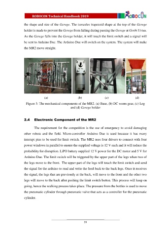
(a) (b) (c) (d)
Figure 3: The mechanical components of the MR2. (a) Base, (b) DC worm gear, (c) Leg
and (d) Gerege holder
2.4 Electronic Component of the MR2
The requirement for the competition is the use of emergency to avoid damaging
other robots and the field. Micro-controller Arduino Due is used because it has many
interupt pins to be used for limit switch. The MR2 uses four drivers to connect with four
power windows in parallel to ensure the supplied voltage is 12 V each and it will reduce the
probability for disruption. LiPO battery supplied 12 V power for the DC motor and 5 V for
Arduino Due. The limit switch will be triggered by the upper part of the legs when two of
the legs move to the front. The upper part of the legs will touch the limit switch and send
the signal for the arduino to read and write the feed-back to the back legs. Once it receives
the signal, the legs that are previously at the back, will move to the front and the other two
legs will move to the back after pushing the limit switch button. This process will keep on
going, hence the walking process takes place. The pressure from the bottles is used to move
the pneumatic cylinder through pneumatic valve that acts as a controller for the pneumatic
cylinder.
59