
Page 71 - Robot Design Handbook ROBOCON Malaysia 2019
P. 71
2.2 Electrical Design
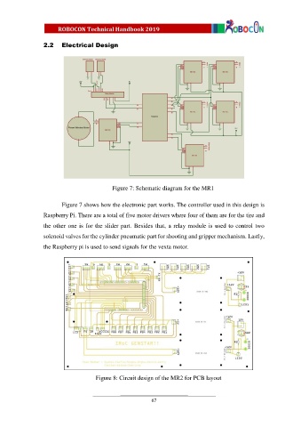
Figure 7: Schematic diagram for the MR1
Figure 7 shows how the electronic part works. The controller used in this design is
Raspberry Pi. There are a total of five motor drivers where four of them are for the tire and
the other one is for the slider part. Besides that, a relay module is used to control two
solenoid valves for the cylinder pneumatic part for shooting and gripper mechanism. Lastly,
the Raspberry pi is used to send signals for the vexta motor.
Figure 8: Circuit design of the MR2 for PCB layout
67