
Page 92 - demo
P. 92
BOOK IN SERIES
thrusts. Old and expensive types of gear pumps (made
up of perfectly smooth lateral faces and a stator with very
precise shim adjustments) were replaced by radial and axial
compensation pumps, also known as self-balancedpumps,
which consist of a casing and balancing bushings made of
aluminium alloy, treated steel gearwheels and front seals
made of reinforced nitrile mixture or viton.
Axial and radial compensations are made possible by placing
two balancing or compensation bearings opposite the plane
faces of the gearwheels and axially floating between the
covers and the gears themselves.
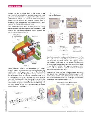
Figure 4.10
Radial balance design must also take into account the fact
that teeth in mesh cannot fully expel oil. As a result, tiny
fluid drops are ‘squeezed’ between the engaging wheels,
thus entailing (depending on the incompressibility of the
liquid) local overpressures that act in a radial manner vis-à-
Figure 4.8 vis gear shafts. In addition, during gear disengagement, the
Inaxial andradial balance, the pressurised fluid, pushed volume between the teeth suddenly increases even before
through tiny and accurately measured openings between the the contact with the sucked fluid.
outlet and the bushings, exerts a thrust on their two back Consequently, the central part of bushings must have some
parts (cover sides). This keeps them solidly connected to interstices in order to discharge this fluid; these are the only
the wheel but it allows an adequate lubrication thanks to an points where delivery and suction areas come into contact
accurate design of the thrust force. As a result, gears perfectly and the overpressure-prone fluid discharges in micro-areas
mesh with bushings while the lubricating film prevents the subjected to early vacuum (Figure 4.11).
faces of the parts from wearing out; the spindles solidly
connected to the gearwheels do not need more bearings and
the single bearing, if used, is positioned over the end of the
transmission shaft (Figure 4.10).
92
Figure 4.9 Figure 4.11
www.ghmediabusiness.com
| Global MDA Journal | NOV-DEC 2017