
Page 93 - demo
P. 93
BOOK IN SERIES
Some systems need the direction reverse of the prime
mover but their wheels cannot be inverted; under these
circumstances gear pumps known as reversible pumps are
employed because their inlets can turn into the outlets and
vice versa as they have the same bore.
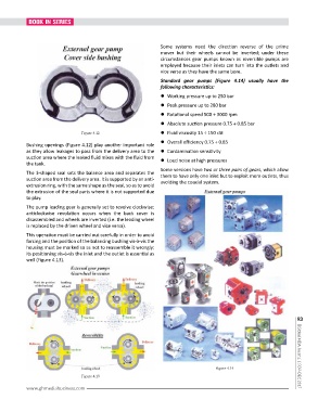
Standard gear pumps (Figure 4.14) usually have the
following characteristics:
l Working pressure up to 250 bar
l Peak pressure up to 280 bar
l Rotational speed 500 ÷ 3000 rpm
l Absolute suction pressure 0.75 ÷ 0.85 bar
Figure 4.12 l Fluid viscosity 15 ÷ 150 cSt
l Overall efficiency 0.75 ÷ 0.85
Bushing openings (Figure 4.12) play another important role
as they allow leakages to pass from the delivery area to the l Contamination sensitivity
suction area where the leaked fluid mixes with the fluid from l Loud noise at high pressures
the tank.
Some versions have two or three pairs of gears, which allow
The 3-shaped seal sets the balance area and separates the them to have only one inlet but to exploit more outlets, thus
suction area from the delivery area. It is supported by an anti- avoiding the coaxial system.
extrusion ring, with the same shape as the seal, so as to avoid
the extrusion of the seal parts where it is not supported due
to play.
The pump leading gear is generally set to revolve clockwise;
anticlockwise revolution occurs when the back cover is
disassembled and wheels are inverted (i.e. the leading wheel
is replaced by the driven wheel and vice versa).
This operation must be carried out carefully in order to avoid
forcing and the position of the balancing bushing vis-à-vis the
housing must be marked so as not to reassemble it wrongly;
its positioning vis-à-vis the inlet and the outlet is essential as
well (Figure 4.13).
93
Figure 4.14 | Global MDA Journal | NOV-DEC 2017
Figure 4.13
www.ghmediabusiness.com